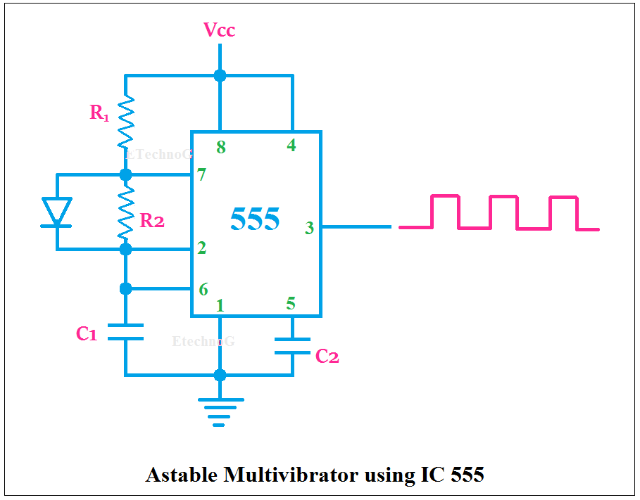
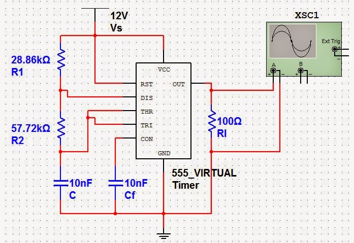
555 Astable Circuit Diagram
555 timer math Astable multivibrator circuit 555 ic using diagram applications output cycle duty here advantages r1 varied pulses resistance varying 555 timer astable multivibrator circuit diagram
Astable Multivibrator using 555 IC
555 timer astable mode circuit pwm duty cycle control voltage schematic variable using resistor output basics lab public step input Astable multivibrator using 555 timer Astable multivibrator using 555 timer
555 astable circuit circuits timer lm ic mode multivibrator explained diagram monostable using simple application tracking infrared system ir operation
555 timer led astable mode flashing circuit blinking potentiometer using resistor photoresistor capacitor light basics flash circuitbasics diagram make ohmAstable circuits 555 timer led astable mode flashing circuit blinking using resistor potentiometer capacitor photoresistor light basics circuitbasics flash diagram make ohm555 astable circuits circuit 1khz multivibrator operation volts.
555 astable multivibrator timer ic using circuit diagram ne circuits output led electronics working waveform555 timer ltspice astable circuit schematic math figure mathscinotes Metronome using astable mode of 555 timer icAstable oscillator circuit : oscillator circuits :: next.gr.

555 astable timer circuit multivibrator diagram mode ic circuits pulse operation using clock trigger electronics circuitdigest generated timers electronic here
555 astable timer multivibrator circuit using diagram ic mode circuitstoday555 astable ic using circuit multivibrator practical 555 astable ic circuit circuits homemade formulas explored bistable pinouts monostable timer multivibrator basic here modesAstable 555 multivibrator timer.
Ready to help: astable multivibrator using ic 555555 timer basics 555 timer basicsAstable 555 timer schematic.

555 astable circuit ic multivibrator timer using pulse generator diagram light help circuits sensor audio make connect pc here chip
Making astable multivibrator using 555 timer ic555 timer astable multivibrator circuit diagram 555 timer circuit ic diagram astable mode tutorial introducingIc 555 pinouts, astable, monostable, bistable modes explored.
555 timer basics555 astable timer ic mode circuit metronome using diagram projects project Astable circuit three oscillator gr next diagram circuits shown seen level each555 astable circuit timer schematic calculator works using tools allaboutcircuits disconnect jumper touch only when overview.

Best of 555 timer application circuits explained
555 timer ic diagram block astable multivibrator circuit using internal555 astable multivibrator timer circuit board diagram circuits breadboard ic monostable mode projects electronics circuitdigest radio arduino choose Astable multivibrator applications, advantages and circuit diagramAstable multivibrator using 555 timer.
555 astable timer circuit multivibrator diagram using oscillator diode circuits voltage regulator inputAstable circuit 555 led gif off detail repeated completely pulses switched until because three power technologystudent elec1 Astable multivibrator using 555 icCircuit design 555 astable circuit.

555 timer astable multivibrator circuit diagram
Astable 555 circuit circuits oscillator electronicsTinkercad 555 astable circuit Astable multivibrator using ne 555 timer ic -circuit diagram andThe 555 astable circuit.
555 astable timer circuit instructables tutorial lm555 datasheet dischargeIntroducing 555 timer ic ‘555’ astable circuits555 timer astable circuit and equations.

555 timer astable oscillator circuit
555 astable circuit diagram timer multivibrator circuits calculator using electronic mode led time off formulas cycle fullAstable 555 timer circuit equations .
.


