Electronic Clock Circuit Diagram
Clock digital circuit ic using 555 diy diagram segment display project electronics arduino board projects ics hub above resolution high Simple led clock circuit diagram Digital clock circuit using ic 555 and ic 4026 – diy electronics projects
Arduino Based Digital Clock With Alarm Using 1602 LCD: 4 Steps
555 clock timer circuit circuitos schematic build con using learningaboutelectronics 60hz resistor esquemas will breadboard produce shown below 16f84 fyp Led circuits timer witnessed
How to build a clock circuit with a 555 timer
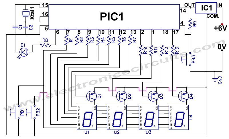
Fyp: digital clock circuitArduino based digital clock with alarm using 1602 lcd: 4 steps Make digital clock & learn pic microcontroller programmingArduino circuito lcd baseado despertador elforum ds1307 major circuitdigest.
.


