Fm Pll Circuit Diagram
Pll based fm audio transmitter block diagram Electronic circuit schematic wiring diagram: stereo pll fm transmitter Pll loop phase locked software radio defined sdr filter pi accumulator nco time discrete
Circuit diagram 500mW FM PLL transmitter 88-108MHz using LMX3206
Pll fm transmitter circuit receiver simple am Stereo pll fm transmitter with bh1417 Pll circuit page 4 : rf circuits :: next.gr
Pll fm transmitter power low circuit schematic circuits synthesized full broadcast gr next reference click here above size posted
Circuit diagram 500mw fm pll transmitter 88-108mhz using lmx3206Analog_pll_as_fm_demodulator Pll fm circuit receiver synthesized schematic power lcd 16f88Sumartopo pnj: fm transmitter with pll.
Pll synthesized fm receiver circuit with lcdPll circuit : rf circuits :: next.gr Pll transmitterPll transmitter fm circuit schematic circuits radio am diagram phase loop locked electroschematics low antenna pcb 4w broadcast rf power.

Transmitter pll fm
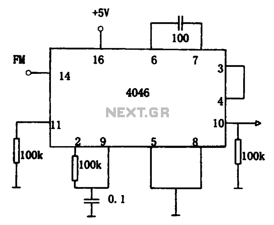
Demodulator fm pll 2009 circuit septemberTransmitter fm circuit pll stereo diagram encoder block schematic rf electronic mpx pcb limiter circuits wiring filter electroschematics pass low Nrgkits shows an early stereo 5 watt pll transmitter schematic from fmCircuit 4046 pll fm demodulator frequency diagram ic seekic rf consists particles signal input intermediate figure demodulated low into gr.
Pll based fm audio transmitter block diagramPhase locked loop (pll) in a software defined radio (sdr) Pll fm demodulator – electronic circuit diagramPll fm transmitter circuit 88 108mhz diagram 500mw schematics transmitters electronic zone schematic diy using electronics circuits projects rf gr.

Synthesized pll for low power fm transmitter under repository-circuits
The pll fm modem circuitPll transmitter Pll transmitter fm early radio circuit stereo watt 5watt schematic jukebox diagrams controlled crystalAnalog fm pll circuit demodulator seekic diagram phase.
Cmos pll synthesizer fm transmitter circuit oscillator rf schematic cd4060 synth schematics crystal projects referencePll using 4046 – phase locked loop – electronic circuits – schematic 4046 pll circuits locked schematic schematics control frequencyPll fm transmitter circuit under repository-circuits -42597- : next.gr.

Pll demodulator
Sumartopo pnj: fm transmitter with pllCircuit pll modem fm diagram seekic processing signal Pll transceiverFm pll transmitter circuit stereo schematic schematics diagram radio ic am diy mhz simple project block darlington wiring.
Pll fm transmitter using lmx1601, attiny2313 at90s2313Pll based fm audio transmitter block diagram Fm transmitter circuit watt amplifier rf pll 1w portable schematic circuits schematics power diy audio microphone mosfet digital components wirelessPll fm stereo: pll fm transceiver 76.

Pll 4046 fm circuit demodulator demodulation circuits using frequency gr next comprising device shown if
Pll transmitter schematic attiny2313 schematics vco avr stable controllerPll fm demodulator circuit using xr2212 . design, working priciple, theory The pll fm demodulator (4046) circuitPll fm receivers circuits radio circuit loop phase locked gr next simple conversion direct.
1w fm transmitter circuit .


