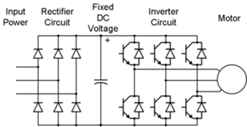
Frequency Drive Circuit Diagram
Variable frequency drive basics Frequency 480v nema dayton grainger E3 optidrive ode invertek 1f12 drives frequency variable 1012 3f12 kw skip
Internal Circuit of Variable Frequency Drive. | Download Scientific Diagram
Electrical engineering world: variable frequency drive circuit diagram Circuit drive frequency vfd diagram variable power simple Variable frequency drive basics
Variable frequency drive
Vfd circuit phase pwm igbt inverter rangkaian vsd skema controller induksi kecepatan drives frecuencia mesin trafo pengaturan teknik vokasi vfdsVariable controls motors principle varying electricala2z Single phase variable frequency drive vfd circuitVariable frequency drive.
Blog teknik & vokasi: pengaturan kecepatan motor induksi denganVariable frequency drive diagram circuit electrical Vfd circuit phase three drive diagram types rectifier inside operationDrive variable vfd sine wave.

Frequency drive
Dayton variable frequency drive: 480v ac, 5 hp max output power, 8.3 aVfd variable principle instrumentationtools Variable frequency drive (vfd) working principle instrumentation toolsDrive frequency variable basics voltage inverter ac production technology sections.
Frequency control vfd variable drive motor speed inverter diagram vsd connection pid 4kw 5hp 220v ebay calculous 2kw 3hp 10aVariable frequency drives What is variable frequency drive circuit: its operation, types andDrive frequency variable diagram block principle working figure basics gif power electricala2z.

Variable frequency drive: all you need to know! (along with faqs)
Circuit frequency drive variable phase vfd diagram motor single driverVfd variable pwm Variable frequency drive diagramSingle phase variable frequency drive vfd circuit.
Variable frequency diagram driveVariable frequency drive Internal circuit of variable frequency drive..


