Frequency Response Circuit Diagram
Frequency response comparison Low pass frequency response of the simple genetic circuit, figure 9 Frequency response sound impulse graph graphs figure analysis phase vs example digital delay system signal digitalsoundandmusic music
Low pass frequency response of the simple genetic circuit, Figure 9
Frequency response specifications technical diagram adt audio Frequency response tutorial and circuits Frequency response tutorial and circuits
Frequency response
Frequency response instrumentation phys modern ppt powerpoint presentation chemFrequency modulation Resonance rlc resonant frequency curve frequenciesStub frequency response.
Frequency response of op-amp circuitsSolved: the frequency response curve for an rlc circuit is... Cgd responseOp amp differentiator : circuit, frequency response & its working.

Frequency response of led. the frequency response measured by network
Stub response frequency circuit simulatorCircuit rc series analysis parallel response frequency electrical4u transfer function equations Rc circuit analysis: series & parallel (explained in plain englishResponse frequency curve measurement test tutorial frequencies fall low high.
Frequency modulationSeries resonance in a series rlc resonant circuit Response frequency circuitlab comparison circuit descriptionCircuits frequency circuit.

Solved d) figure 3 shows the high frequency response circuit
Anti-hum filter circuit for 60 hzResponse circuit curve rlc frequency diagram determine shown below solved Frequency differentiator circuitSimple rc low pass filter circuit diagram with frequency response.
Sauro herbertDiagram frequency response Frequency response tutorial measurement test times amplification output amplifier greater shown above give perfect than wouldMeasured analyzer theoretical dmt constraints.

Frequency response lr circuit at rs 2200/piece(s)
Simple tone control circuitsChapter 2 – digital sound & music Frequency modulation modulated wave equation definition representation byjus graphical frequenciesCircuit response filter frequency hz hum anti components.
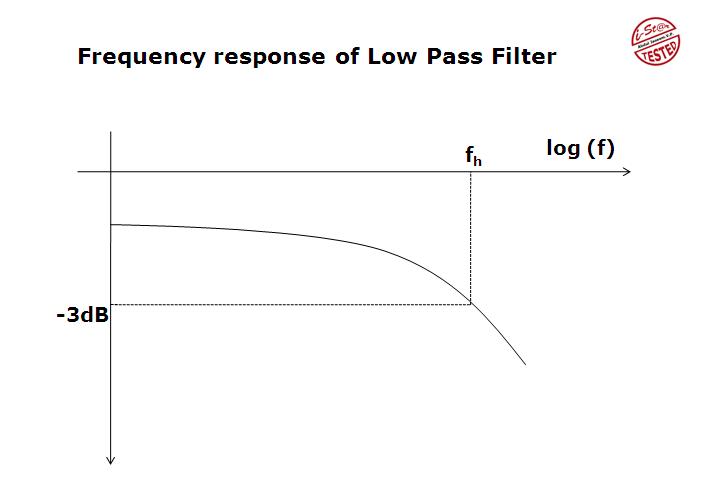
Pass low frequency response filter circuit rc diagram integrator simple enlarge click .


